| home > camera work > coolpix e990 USB and serial cable |
|
 How to make a dual USB and serial cable from the
Nikon Coolpix E990 USB cable.
How to make a dual USB and serial cable from the
Nikon Coolpix E990 USB cable.
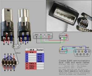
Use this information at your own risk... AWM E148000 STYLE 20276 80C VW-1 LTK FULLY-RATED-SPEED USB(SHIELDED) 28AWGX1P+28AWGX2C implying that this is a 4-wire cable with 1 twisted pair and two other conductors. Thus the remaining 4 pins are free and indeed represent the connections for a serial cable. This web page documents the project of converting the supplied USB cable into a dual-purpose USB/serial cable. IMPORTANT NOTE: This project requires work on a very dense connector with 28 gauge wire (very fine) as well as soldering in very close quarters. Be certain that this project is within your abilities before cutting up your cable; Take a close look at the pictures and compare them to your UC-E1 cable to get a sense of how small this connector is!
Per Madsen is working on some
programs
(Windows only / no source is available) for controlling the E990 via the serial cable and also
posted
a nice diagram of the serial connector wiring. Per plans to charge for his software and it currently requires you to register or
wait for a timeout when loading and for each snapshot. Also the downloads are rather slow but this is being worked on.
Charlie Wallace also has a program,
cPix
, (Windows only / no source is available) which uses the USB connection instead. In fact my camera and laptop don't like
NikonView via USB at all but work just fine with the USB photopc and cPix.
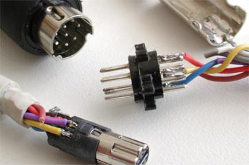
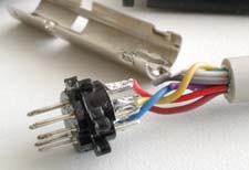
By slowing working on this injected plastic with an X-acto knife and some angle cutters I was eventually
able to free the actual connector assembly inside. I also unsoldered the wires once I had removed enough
material to gain access to the solder points. Doing this allows you to more easily peel off the
remaining injected plastic without having to worry about damaging the solder tags or the wiring.
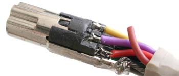
If you are going to make a single "Y" cable by adding wire to the
existing configuration then you may want to leave the existing USB wires soldered to the connector, but
you will need to be certain that none of the wiring has been damaged during the plastic removal. | ||||||||||||
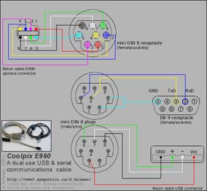
 Once all the extra plastic is removed and the wires unsoldered, the rebuilding can begin. It is important
to note here that the serial communication link includes a short (electrical connection) between 2 of the pins on
the camera's communication connector. This is how the camera seems to identify the serial cable connection. In making
a dual-purpose cable, there is the need to ensure that only one type of communication connection is made at a time.
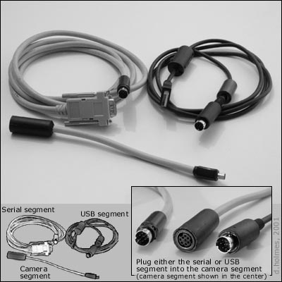
This is the primary reason I decided to make a multi-segment cable instead of a one-piece cable with a switch.
I chose miniature DIN-8 connectors for joining the segment halves together.
Once all the extra plastic is removed and the wires unsoldered, the rebuilding can begin. It is important
to note here that the serial communication link includes a short (electrical connection) between 2 of the pins on
the camera's communication connector. This is how the camera seems to identify the serial cable connection. In making
a dual-purpose cable, there is the need to ensure that only one type of communication connection is made at a time.
This is the primary reason I decided to make a multi-segment cable instead of a one-piece cable with a switch.
I chose miniature DIN-8 connectors for joining the segment halves together.
There are two diagrams at the bottom of this page which include all the circuit information and drawings needed to make a multi-segment cable. The following items are needed to make this dual-purpose cable:
I have now done some initial testing with this new cable setup. Using a laptop I was able to get ~84kbps(kilo bits per second) with the serial cable setup and ~2Mbps with the USB cable setup. NikonView 3.0 and 3.11 were both used for the serial tests and photopc and cPix were both used for the USB tests. For some reason neither version of NikonView works for me with the USB connection. I would prefer to find some better wire to use, particularly for the camera segment and I will need to look at a more permanent method to reclosing the camera connector shell once I'm satisfied with the cable assembly. More news will follow...
| ||||||||||||
| ||||||||||||
|
|
||||||||||||
| < back to the top | ||||||||||||
© 2001, d.holmes
CC BY-SA [Creative Commons Attribution-ShareAlike] (info)
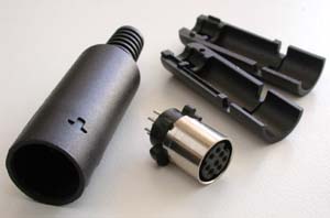
 The first order of business is to open the camera-end of the Nikon-supplied camera-to-USB cable. The outer
plastic shell (cover) of the connector is separate from the inner connector and wire so it is possible
to cut open the cover by carefully slicing along one side. (see the picture at the top of this page)
The first order of business is to open the camera-end of the Nikon-supplied camera-to-USB cable. The outer
plastic shell (cover) of the connector is separate from the inner connector and wire so it is possible
to cut open the cover by carefully slicing along one side. (see the picture at the top of this page)