| home > hardware > simple bus level-shift |
|
 A simple and elegant solution using a MOSFET to level-shift
control and bi-directional data lines between circuits running at different voltages.
A simple and elegant solution using a MOSFET to level-shift
control and bi-directional data lines between circuits running at different voltages.
[2001-12-19; updated 2013-03-02]
While doing some background reading about the Philips I2C bus
I came across an application note written by Herman Schutte (of
Philips Semiconductors Systems Laboratory in Eindhoven). Mr. Schutte described an elegant
mechanism for interfacing sections of I2C-bus which are operating at different
voltages through the use of MOSFETs and pull-up resistors. I had also been
looking at a number of options for
interfacing a 5V LCD panel to a microcontroller system that I
wanted to run at 3V and so decided to try applying this idea
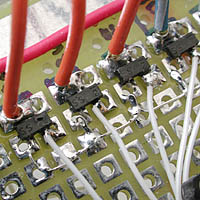
to the data and control lines in my circuit. AT90S8515 @ 3V meets L203400J00 @ 5V Although I was building the circuit by hand I decided to use a surface mount package for the MOSFETs. As three-terminal devices they are relatively easy to solder as long as you can hang onto them. The image above on the right shows some of the 11 MOSFETs in use on the 0.1" proto board. I used the Fairchild Semiconductor BSS138 (product page; Onsemi acquired Fairchild in 2016) N-channel enhancement mode MOSFET which is available in the standard SOT-23 package from folks like Digi-Key. Below on the right are wave forms for the circuit using three different values for the pull-up resistors: 100k, 10k and 4.7k ohms. These values were picked from what I had close at hand. The circuit functions with any of them in fact. |
 A basic drawing for the circuit I'm using is
here.
(or here for browsers without
JavaScript.)
As the schematic shows, the circuit is remarkably simple and straight-forward.
I have this circuit in-use with an ATMEL AT90S8515 (at 3.6864Mhz) controlling
a Seiko L203400J000 20x4 character LCD module. The 8515 is connected to a 3V supply
while the LCD requires 5V. The control lines, RS, RW and E and the data lines D0-D7
are each level-shifted with the BSS138 MOSFETs. The level-shifting imposes no directionality
on the bus so both reading from and writing to the LCD are possible.
A basic drawing for the circuit I'm using is
here.
(or here for browsers without
JavaScript.)
As the schematic shows, the circuit is remarkably simple and straight-forward.
I have this circuit in-use with an ATMEL AT90S8515 (at 3.6864Mhz) controlling
a Seiko L203400J000 20x4 character LCD module. The 8515 is connected to a 3V supply
while the LCD requires 5V. The control lines, RS, RW and E and the data lines D0-D7
are each level-shifted with the BSS138 MOSFETs. The level-shifting imposes no directionality
on the bus so both reading from and writing to the LCD are possible.
An interesting feature of the circuit is that two halfs of the bus can be isolated from each other by pulling the FET gates low. Mr. Schutte describes a number of similar extensions to his basic circuit idea and discusses the necessary MOSFET features as well as some results.
The Philips Semiconductor application note is currently (2010) at:
AN97055
Other folks using Mr Schutte's circuit including versions with the BSS138 MOSFET:
|
© 2001, d.holmes
CC BY-SA [Creative Commons Attribution-ShareAlike] (more info)